ORIGINAL RESEARCH |
https://doi.org/10.5005/jp-journals-10080-1539 |
Comparative Stiffness Characteristics of Ilizarov- and Hexapod-type External Frame Constructs
1,5Department of Trauma and Orthopaedics, Hull University Teaching Hospitals NHS Trust, Hull, East Yorkshire, United Kingdom
2Leeds Teaching Hospitals NHS Trust, Leeds, West Yorkshire, United Kingdom
3,4Department of Trauma and Orthopaedics, Texas Scottish Rite Hospital for Children, Dallas, Texas, United States of America
Corresponding Author: Carl Fenton, Department of Trauma and Orthopaedics, Hull University Teaching Hospitals NHS Trust, Hull, East Yorkshire, United Kingdom, Phone: +07966049169, e-mail: carlfenton@hotmail.co.uk
How to cite this article: Fenton C, Henderson D, Samchukov M, et al. Comparative Stiffness Characteristics of Ilizarov- and Hexapod-type External Frame Constructs. Strategies Trauma Limb Reconstr 2021;16(3):138–143.
Source of support: Nil
Conflict of interest: None
ABSTRACT
Background: The Ilizarov method and fixator are clinically recognised for the treatment of fractures, limb salvage and deformity correction. There have been extensive studies determining the basic mechanism for fracture healing using this technique. It is generally accepted that circular frames optimise the mechanical environment by reducing shear strain across the fracture while maintaining axial micromotion so as to promote fracture healing. There have been several new hexapod-type frames introduced into the market over the past 20 years with little comparative research into their biomechanical properties and resultant effects on the fracture environment.
Questions/purposes: To investigate the biomechanical behaviours of the TrueLok-Hex (TL-HEX) and Taylor spatial frame (TSF) hexapod-type circular external fixators with comparison to traditional Ilizarov-type (TL-Ilizarov and TSF-Ilizarov) constructs and potential performance in vivo.
Methods: Testing was performed on standardised four-ring TSF and TL-HEX constructs matched by identical frames using Ilizarov threaded rod constructs for each set of components. All frames were tested under physiological levels of axial, bending and torsional loading. Load-deformation properties for each construct under each mode of loading were calculated and analysed statistically using ANOVA.
Results: Under axial loading, the Ilizarov construct utilising TL-HEX components demonstrated the greatest rigidity followed by the Ilizarov construct using TSF components. Under bending loads, the difference in rigidity between constructs was similar but less marked. Under torsional loading, both hexapod frames were seen to be significantly more rigid than the Ilizarov constructs. Overall deformation around neutral loading was much higher in the TSF frame due to an observed significant “toe-in” laxity in the strut universal joints. The remaining deformation of both hexapod frames was similar with a higher level of TL-HEX rigidity in axial loading and a higher level of TSF rigidity in bending and torsion.
Conclusion: In conclusion, both hexapod frame constructs were less rigid under axial loading but more rigid under bending and torsional loads than their comparative Ilizarov constructs. As a result of their Cardan universal joints, the TSF demonstrated greater overall planar strain due to the observed “toe-in” laxity around neutral loading while the TL-HEX, with ball-and-socket universal joints, demonstrated a minimal level of laxity. Beyond the initial deformation due to the preloaded laxity, both hexapod frames responded to loading in a similar manner. There were significant differences in the frames’ mechanical behaviour under different loading conditions but further research is required to determine whether these translate in vivo into clinical significance.
Keywords: Biomechanical analysis, Biomechanical study, Biomechanics, Circular external fixation, Circular frame, Taylor spatial frame.
INTRODUCTION
The Ilizarov method and fixator are clinically recognised for the treatment of fractures, limb salvage and deformity correction.1 Extensive studies have described the basic mechanism for fracture healing using this; the frame design reduces shear strain across the fracture while maintaining axial micromotion so as to promote fracture healing.2 There have been several new hexapod-type frames introduced into the market over the past 20 years with little comparative research into their biomechanical properties and resultant effects on the fracture environment. This study aims to compare the biomechanical properties of two of the most commonly used hexapod frames: the TrueLok-Hex (TL-HEX, Orthofix, Verona, Italy) and the Taylor spatial frame (TSF, Smith & Nephew, Memphis, Tennessee), which have significant differences in their design.
During gait, three types of loading forces occur at the fracture site; axial, bending and torsional. Each of these influences the fracture environment especially in the early stages of healing.3 The relationship between fracture site motion and bone formation is dynamic and the strain changes occurring depend on a number of factors including the maturation of the callus and changes of tissue type towards those that limit strain and promote the formation of a bone. Where there are high levels of elongation – more than 10% of the original fracture gap – the fibrous tissue tends to predominate and this in itself reduces inter-fragmentary motion (IFM) thereby adapting the fracture environment and tending towards decreasing levels of strain allowing the development of bone within the callus (occurring when axial elongation is <2%).3
Factors that affect bone healing have been studied, and there is a strong correlation between IFM and callus formation.4 The body of the literature suggests that a degree of axial micromotion at the fracture site is desirable and that this can promote callus formation.5,6 Conversely, excessive motion can impair fracture consolidation, and the degree of allowable strain across the fracture site is controversial.7,8 Some studies have suggested that fracture healing will occur at up to 25% of shear strain9,10 while others suggest that strain delays or impairs healing.11,12 There is no clear consensus in the literature on the effect of torsional strain on fracture site healing although it is thought to be less deleterious than the effects of shear strain.12
Carter et al. (1998) suggested that the differentiation of pluripotent cells in the fracture site was influenced by the early mechanical environment; those within a more stable mechanical environment differentiated into an osteogenic lineage rather than chondrogenic cell types.7 It follows that an axial micromotion in the early phase of healing will produce improved conditions and therefore the aim of any fixation device would be to limit shear strain while maintaining micromotion. There is strong evidence that circular external fixation using fine wires promotes micromotion at the fracture site while limiting the effects of shear strain13 and that a combination of fine wires and pins limits shear strain further.14
Additionally, there are factors in the specific design of frames that may influence fracture movement at the fracture site including strut dimensions and the type of linkage between the ring and struts. The TSF frame, for example, uses a Cardan type of universal joint as a linkage while the TL-HEX fixator uses a captive ball-and-slotted-socket joint (Fig. 1). Other factors that affect the performance characteristics of the frame in vivo include the method of frame assembly, the number of rings used and the arrangement of wires and half pins to secure the bone. A combination of wires and half pins vs fine wires alone has been shown to increase the stiffness of the construct and reduce fracture site movement.14 Fine wires, when used in a circular frame, demonstrate beam-loading characteristics that lead to a low shear strain environment whereas half-pins tend to demonstrate cantilever bending and when used alone are thought to increase fracture site shear strain.14,15 Half-pins increase the torsional stiffness of the construct and have the additional advantage of increasing the anatomical corridors that can be utilised and improve patient comfort.15,16 Fine wires have the advantage of being self-stiffening during increasing loading but can produce muscle irritation.5

Fig. 1: TSF (left) and TL-HEX (right) hexapod strut design. Note the Cardan (TSF) and ball-and-slotted-socket (TL-HEX) type of connecting joint used in each of the struts
The purpose of our study is to examine the biomechanical behaviour of hexapod-type frames with Cardan vs ball-and-socket universal joint of the struts in comparison to traditional Ilizarov-type constructs. We investigated to see whether there was any difference in the mechanical properties of the frames and how this was related to the characteristics of the ring interconnecting components used in the frame construct.
MATERIALS AND METHODS
Conduct of the Tests
The mechanical testing study was designed to evaluate and compare the resulting response of the frames with different types of ring-to-ring interconnecting components to axial, bending and torsional loading in a laboratory setting. To minimise the number of variables, the mechanical performance of the frames was evaluated without the presence of a bone model secured to the rings via fixation elements.
Four frame constructs were used in the study (Figs 2A to D). Two of those frames included two TSF 155-mm diameter double-ring blocks interconnected at 175-mm distance by either six TSF medium struts with Cardan-type universal joints (TSF) or four 6-mm diameter threaded rods (TSF-Ilizarov). Similarly, two further frames were constructed using two TL-HEX double-ring blocks also interconnected by either six TL-HEX struts with slotted socket universal joints (TL-HEX) or four threaded rods (TL-Ilizarov) using equivalent sizes. Each of the frame constructs underwent 10 preconditioning cycles prior to testing followed by a loading/unloading testing cycle, which was repeated 10 times. During each testing cycle, 12 separate data points were recorded producing 120 data points total across each type of frame. The threaded rods, struts and rings were changed across each of the frames tested. In order to produce clinically relevant results, loading parameters were determined from a previous study in the literature which demonstrated that during normal gait up to 70% of ground reaction force is supported as axial load, 2.5% as bending load and another 0.75% as torsion.17 In an 80-kg person, this would be equivalent to 500 N of axial loading, 20 Nm of bending load and 6 Nm of torsional force. In order to test the frames beyond this level, parameters of torsional force to 20 Nm were selected for linearity of results.

Figs 2A to D: Four frame constructs assembled for mechanical testing: (A) TSF; (B) TSF-Ilizarov; (C) TL-HEX; and (D) TL-Ilizarov
Measurement Equipment
We used the Bose ElectroForce 3330 system (Bose Corporation, Eden Prairie, Minnesota) for axial and torsional load testing and the MTS 858 system (MTS, Eden Prairie, Minnesota) for bending loads in order to accommodate the length of the frame construct. The most distal ring of the frames was secured to the test rigs using custom-built jigs. Loads were applied to the most proximal ring to record the resulting deformations (Fig. 3).

Fig. 3: Frame construct positioning for mechanical testing: Axial and torsional loading (left) and bending (right)
Data Analysis
A post hoc analysis using one-way ANOVA followed by Tukey’s multiple comparison test was performed using GraphPad Prism version 7 (GraphPad Software, La Jolla, California, USA). A p <0.05 was considered to be statistically significant. The data were tested to determine the normality of distribution using the Pearson omnibus test, and skew was determined by Q–Q plots. The rigidity of each of the construct was analysed using non-linear regression to determine the slope in the linear-elastic portion of the graph.
RESULTS
Comparative deformation and mean rigidity of the hexapod-and Ilizarov-type frames under axial, bending and torsional loading are presented in Table 1.
| Frame | ||||
|---|---|---|---|---|
| Loading | TL-HEX | TSF | TL-Ilizarov | TSF-Ilizarov |
| Axial loading (N) | Axial deformation (mm) | Axial deformation (mm) | Axial deformation (mm) | Axial deformation (mm) |
| −10 | 0.0 ± 0.0 | 0.1 ± 0.0 | 0.0 ± 0.0 | 0.0 ± 0.0 |
| 0 | 0.0 ± 0.0 | 0.0 ± 0.0 | 0.0 ± 0.0 | 0.0 ± 0.0 |
| 10 | 0.0 ± 0.0 | 0.2 ± 0.0 | 0.0 ± 0.0 | 0.0 ± 0.0 |
| 500 | 1.6 ± 0.0 | 2.1 ± 0.0 | 0.5 ± 0.0 | 1.0 ± 0.0 |
| Rigidity (N/mm) | 407.9 ± 42.2 | 366.2 ± 4.5 | 942.4 ± 16.3 | 514.6 ± 6.7 |
| Mean difference in rigidity | 41.7; 95% CI 30.8–52.6; p <0.01 | Mean difference in rigidity | 427.8; 95% CI 416.9–438.7; p <0.01 | |
| Bending loading (Nm) | Bending deformation (°) | Bending deformation (°) | Bending deformation (°) | Bending deformation (°) |
| –5 | –0.1 ± 0.0 | –0.5 ± 0.0 | –0.1 ± 0.0 | –0.1 ± 0.0 |
| 0 | 0.0 ± 0.0 | 0.0 ± 0.0 | 0.0 ± 0.0 | 0.0 ± 0.0 |
| 5 | 0.1 ± 0.0 | 0.1 ± 0.0 | 0.1 ± 0.0 | 0.1 ± 0.0 |
| 20 | 0.3 ± 0.0 | 0.3 ± 0.0 | 0.3 ± 0.0 | 0.3 ± 0.0 |
| Rigidity (Nm/°) | 63.3 ± 7.2 | 68.6 ± 5.1 | 73.7 ± 5.2 | 62.7 ± 3.5 |
| Mean difference in rigidity | 5.3; 95% CI 1.5–9.1; p <0.01 | Mean difference in rigidity | 11.0; 95% CI 7.2–14.8; p <0.01 | |
| Torsional loading (Nm) | Torsional deformation (°) | Torsional deformation (°) | Torsional deformation (°) | Torsional deformation (°) |
| −5 | −0.3 ± 0.0 | −0.5 ± 0.0 | −0.5 ± 0.0 | −0.5 ± 0.0 |
| 0 | 0.0 ± 0.0 | 0.0 ± 0.0 | 0.0 ± 0.0 | 0.0 ± 0.0 |
| 5 | 0.2 ± 0.0 | 0.8 ± 0.0 | 0.5 ± 0.0 | 0.5 ± 0.0 |
| 20 | 0.8 ± 0.0 | 1.3 ± 0.0 | 1.9 ± 0.0 | 1.9 ± 0.0 |
| Rigidity (Nm/°) | 27.8 ± 2.7 | 31.8 ± 6.3 | 10.6 ± 0.2 | 10.2 ± 0.3 |
| Mean difference in rigidity | 4.1; 95% CI 1.7–6.4; p <0.01 | Mean difference in rigidity | 0.4; 95% CI −1.9 – 2.7; p = 0.97 | |
Axial Loading
During axial loading (Fig. 4), both Ilizarov-type constructs with threaded rods underwent similar linear axial deformation demonstrating the greatest rigidity of the construct utilising TL-HEX components. The TSF and TL-HEX constructs with hexapod struts underwent a non-linear deformation with a degree of “toe-in” laxity observed around neutral loading between −10 N and 10 N in both hexapod frames. “Toe-in” laxity refers to the condition when the displacement of one ring of the frame relative to the opposing ring changes through the loading cycle disproportionately to the applied load. This laxity was noticeably less in the TL-HEX frame. The mean displacement created by “toe-in” of the TL-HEX and the TSF between −10 N and 10 N was 0.07 and 0.31 mm, respectively (mean difference 0.24 mm; 95% CI 0.24–0.25; p <0.01). The remaining rigidity of each frame was calculated for the linear part of the curve in order to minimise the influence of this toe-in effect on the analysis of the constructs. Both the TL-Ilizarov and TSF-Ilizarov frames demonstrated greater rigidity, measured at 942.4 ± 16.3 N/mm (95% CI 929.7–958.8) and 514.7 ± 6.7 N/mm (95% CI 509.4–520.0), respectively. The mean difference in rigidity was 427.8 N/mm (95% CI 416.0–438.7; p <0.01). There was also a statistically significant difference of 41.7 N/mm (95% CI 30.8–52.6; p <0.01) in the rigidity between the TL-HEX and TSF hexapod frames with the rigidity measured at 407 ± 42.2 N/mm (95% CI 370.3–508.4) and 366.2 ± 4.5 N/mm (95% CI 362.2–370.4), respectively.
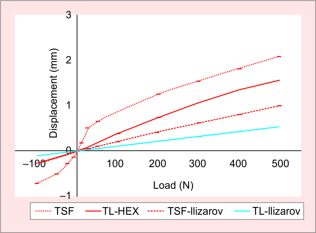
Fig. 4: Load-deformation curves for axial loading
Cantilever Bending
In cantilever bending (Fig. 5), the TL-Ilizarov frame was more rigid than the others, showing increased resistance to angular deformation. The TL-HEX, TSF and TSF-Ilizarov constructs reacted to cantilever bending similarly although the overall angular deformation was higher in the TSF due to the observed “toe-in” laxity as seen in the axial tests. The mean displacement created by “toe-in” of the TL-HEX and the TSF between −5 Nm and 5 Nm was 0.17° and 0.18°, respectively (mean difference 0.02°; 95% CI 0.01–0.02°; p <0.01). It was also noted that the curves were asymmetrical between compression and tension and that this difference was due to the tests being performed with a horizontally positioned fixator in order to accommodate the frame within the testing mounts. This indicated that the weight of the frame “preloaded” the constructs and that laxity was then observed only in the direction away from gravity. The TL-Ilizarov was the most rigid of the frames at 73.7 ± 5.2 Nm/° followed by the TSF at 68.6 ± 5.1 Nm/°. The TL-HEX and the TSF-Ilizarov had a bending rigidity of 63.3 ± 7.2 Nm/° and 62.7 ± 3.5 Nm/°. The mean difference between the TL-HEX and TSF frames was 5.3 Nm/° (95% CI 1.5–9.1; p <0.01) and between the TL-Ilizarov and TSF-Ilizarov was 11 Nm/° (95% CI 7.2–14.8; p <0.01).
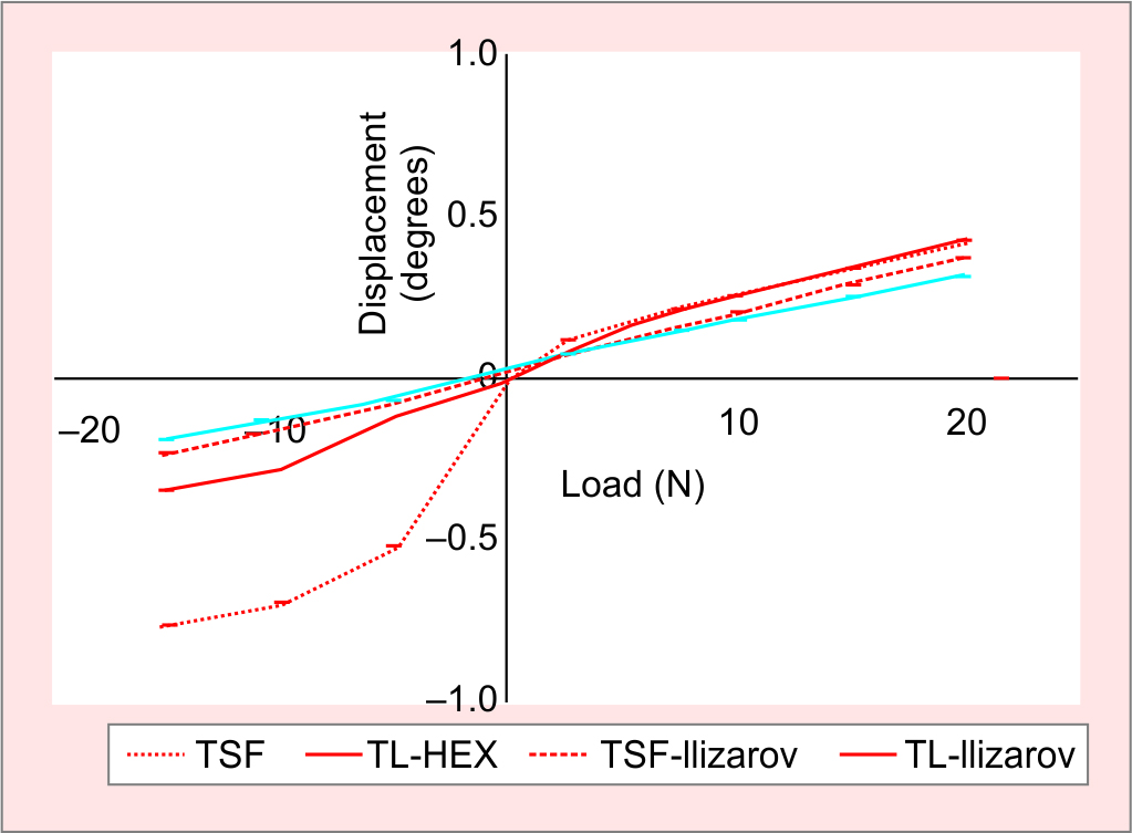
Fig. 5: Load-deformation curves for cantilever bending. Note asymmetrical curve shapes due to horizontal frame positioning resulting in frame “preloading”
Torsional Loading
Under torsional loads (Fig. 6), the hexapod frames were significantly more rigid than the Ilizarov-type constructs with the TSF rigidity recorded at 31.8 ± 26.3 Nm/° (95% CI 13.61–38.52) and the TL-HEX at 27.8 ± 2.7 Nm/° (95% CI 19.84–31.91). The rigidity of the TL-Ilizarov was 10.6 ± 0.2 Nm/° (95% CI 10.29–10.74) and the TSF-Ilizarov was 10.2 ± 0.3 Nm/° (95% CI 9.89–10.36). The observed difference in the rigidity between the hexapod fixators was statistically significant with a mean difference of 4.1 Nm/° (95% CI 1.7–6.4; p <0.01). There was no statistical difference in the rigidity of Ilizarov-type constructs. The TSF frame showed “toe-in” laxity between −5 Nm and 5 Nm. A similar effect was visible with the TL-HEX curve but to a much lesser degree. The mean displacement due to toe-in between the TL-HEX and the TSF was between −5 Nm and 5 Nm was 0.53° and 1.2°, respectively (mean difference 0.71°; 95% CI 0.69–0.72; p <0.01).
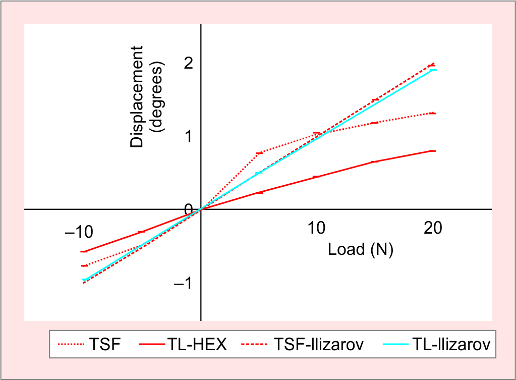
Fig. 6: Load-deformation curves for torsional loading
DISCUSSION
Despite the widespread use of these studied frames in the clinical environment, little comparative testing has been performed to determine the biomechanical differences that may affect their performance in vivo. The primary aim of this study is to answer the question: are there differences in the mechanical properties of the hexapod frames with different types of struts and how are these affected by substituting the hexapod struts by traditional Ilizarov components (threaded rods)?
The result of the biomechanical testing presented here demonstrates that an Ilizarov-type frame configuration, with four threaded rods, is significantly more rigid than a comparative hexapod construct under axial and bending loading. The TL-Ilizarov construct was observed to be 83% more rigid than the TSF-Ilizarov frame under axial loading and 18% under bending loading. This is almost certainly due to dimensional differences between the TL-HEX and TSF rings in width (15.5 and 15.0 mm, respectively) and height (9.5 and 8.0 mm, respectively). In a comparative study using a simulated bone fracture model,18 a similar pattern of characteristics was observed with frame constructs using Ilizarov components showing higher rigidity in axial and bending loading. Similarly, the 6-telescopic strut hexapod frames in the present study demonstrated 2–3 times greater rigidity in a study than 4-threaded rod Ilizarov-type frames in torsion with no significant difference between the TL and TSF Ilizarov-type constructs. This weakness may be considered clinically by replacing the long regular threaded rods with Ilizarov-type telescopic rods or hexapod struts to increase the torsional rigidity of the construct.
Biomechanical testing of the hexapod frame configurations demonstrated 12% greater rigidity of the TL-HEX frame under axial loading compared to that of the TSF. Under bending and torsional loading, however, the rigidity of the TSF frame was greater than that in the TL-HEX frame by 8% and 14%, respectively. In addition, the TSF frame demonstrated a greater level of overall ring displacements under all three loading modes (Figs 4 to 6) due to the “toe-in” laxity seen around neutral loading. This laxity may be explained by the strut design of the TSF hexapod frame utilising very flexible Cardan universal joints. Conversely, the TL-HEX struts utilise more stable ball-and-socket universal joints, and though similar “toe-in” laxity was observed in TL-HEX frames, the degree of deformation produced by this was minimal.
Study Limitations
There are several limitations to the current study. Firstly, the design of the model, although not truly representative of performance in vivo, is an accurate comparator of mechanical performance and characteristics of the frames and constructs tested. Additionally, although the models were tested multiple times, only one version of each construct was used. This therefore carries the risk that any observed mechanical characteristic may be peculiar to that model and issues with its components or construction and may not therefore be representative of the frame design as a whole. Although the differences in frame rigidity and deformation under load may be considered statistically significant, in vivo these differences may be less marked as the addition of fixation elements would diminish the effects seen in our frame-only model. Other factors may also affect the performance in vivo, such as “preloading” of the frame due to soft tissue tension and muscle contraction during the gait cycle. Other factors are also likely to influence the mechanical behaviour including the design of the construct, the distance between the rings and the angle of the struts. The latter has been shown, in some cases, to cause extreme instability where the strut angles are less than 30° in the TSF and these should be avoided.19 Moreover, it has been shown that the magnitude of frame instability in the hexapods with the Cardan joints is inversely proportional to the angle between the rings and struts as well as the distance between the rings. Hexapod frames with ball-and-socket universal joints have superior frame stability independent of ring-to-strut angle and ring separation distance.20
Secondly, a uniform model was used in the present study but it must be recognised that there will be significant variation in the frame constructs in the clinical setting and this may have at least some effect on IFM, especially where the frame construct consists of wires only. Despite this, it has been shown in this and previous studies that the amount of motion is well within the parameters required for bone healing.14,21 Finally, the hexapod frames in the present study have been shown to have greater rigidity in torsion than the Ilizarov-type frames. In the opinion of the authors, the small difference in shear seen in torsional loading would be unlikely to have any great effect on the overall magnitude of shear at the fracture site14,21 compared to that seen in bending loading.
Clinical Relevance
The findings of this study may confer guidance to clinicians in determining the specific directional rigidity of external circular fixation required in a specific clinical situation. In cases where there is a requirement for increased torsional stability, the hexapod frames may provide an advantage due to their better resistance to torsional loading. In cases where there is a requirement for higher axial stability, then the Ilizarov-type constructs may provide better tolerance to increased axial loading. The associated weakness of those constructs to torsion should be improved by replacing the long regular threaded rods with the Ilizarov-type telescopic rods or hexapod struts that have been shown, in our study, to increase the torsional resistance.
Hexapod frames, with reference to the results presented here, may have a particular advantage in bone formation, i.e. in the early phases of fracture healing. Certain levels of axial micromotion are required in the early part of healing in order to stimulate the formation of callus.3,6,22 Some studies have suggested that the healing environment is dynamic and that decreasing levels of motion at the fracture site is required as healing progresses to allow maturation of the bone.23,24 The amount of inter-fragmentary movement in a fracture gap is dynamic and is also influenced by the type of tissue formed as a response to the strain across a fracture gap.3 The fibrous tissue tends to occur where the strain is greater than 10% of the original fracture gap and this itself will influence inter-fragmentary movements,3 thereby adapting the fracture environment and tending towards decreasing levels of strain. Although the results have not been tested on a fracture or animal model, conversion of any of these frames from the hexapod configuration, following any deformity correction, to an Ilizarov-type construct increases the fixator rigidity. This may reduce the overall IFM which, in turn, may benefit the progression of the fracture from fibrous tissue to bone.24
CONCLUSION
In conclusion, this study demonstrated a difference in the mechanical properties of the Ilizarov- and hexapod-type circular external fixation frames, in keeping with the findings of other studies in the literature. Ilizarov-type frames provide higher rigidity in axial and bending loading while the hexapod frames are more rigid in torsional loading. Hexapod frames with cardan-type universal joints of their struts, such as the TSF, are characterised by a significant “toe-in” laxity under axial, bending and torsional loading modes. This is observed around transitional loading from compression to tension. Hexapod frames utilising ball-and-socket universal joints demonstrate minimal levels of laxity. Beyond this initial deformation, due to laxity in the struts, both hexapod frames responded to loading in a similar manner. There was greater rigidity under axial loading demonstrated in the ball-and-socket joints of the TL-HEX and greater rigidity under bending and torsion with the Cardan joints of the TSF. The next obvious step in this area of research would be the introduction of the frames into a fracture/human model to determine whether these observed differences correlate with fracture motion and subsequent healing.
ACKNOWLEDGMENTS
Authors thank Bill Pierce (Senior Engineer) and Melissa Wallace in the Engineering Department at Texas Scottish Rite for their valued technical assistance with the setup of the tests and testing equipment.
MANUFACTURERS
TrueLok-HEX (TL-HEX, Orthofix, Verona, Italy)
Taylor spatial frame (TSF, Smith & Nephew, Memphis, Tennessee, USA)
GraphPad Prism version 7 (GraphPad Software, La Jolla, California, USA)
Bose ElectroForce 3330 system (Bose Corporation, Eden Prairie, Minnesota, USA)
MTS 858 system (MTS, Eden Prairie, Minnesota, USA)
ORCID
Alexander Cherkashin https://orcid.org/0000-0002-0422-9158
REFERENCES
1. Henderson DJ, Barron E, Hadland Y, et al. Functional outcomes after tibial shaft fractures treated using the Taylor spatial frame. J Orthop Trauma 2015;29(2):e54–e59. DOI: 10.1097/BOT.0000000000000192.
2. Glatt V, Evans CH, Tetsworth K. A concert between biology and biomechanics: the influence of the mechanical environment on bone healing. Front Physiol 2016;7:678. DOI: 10.3389/fphys.2016.00678.
3. Perren SM. Physical and biological aspects of fracture healing with special reference to internal fixation. Clin Orthop Relat Res 1979;(138):175–196. PMID: 376198.
4. Claes L, Augat P, Suger G, et al. Influence of size and stability of the osteotomy gap on the success of fracture healing. J Orthop Res 1997;15(4):577–584. DOI: 10.1002/jor.1100150414.
5. Aro HT, Chao EY. Bone-healing patterns affected by loading, fracture fragment stability, fracture type, and fracture site compression. Clin Orthop Relat Res 1993;(293):8–17. PMID: 8339513.
6. Goodship AE, Kenwright J. The influence of induced micromovement upon the healing of experimental tibial fractures. J Bone Joint Surg Br 1985;67(4):650–655. DOI: 10.1302/0301-620X.67B4.4030869.
7. Carter DR, Beaupre GS, Giori NJ, et al. Mechanobiology of skeletal regeneration. Clin Orthop Relat Res 1998;(355 Suppl):S41–S55. DOI: 10.1097/00003086-199810001-00006.
8. Claes L, Wolf S, Augat P. [Mechanical modification of callus healing]. Chirurg 2000;71(9):989–994. DOI: 10.1007/s001040051172.
9. Bishop NE, van Rhijn M, Tami I, et al. Shear does not necessarily inhibit bone healing. Clin Orthop Relat Res 2006;443:307–314. DOI: 10.1097/01.blo.0000191272.34786.09.
10. Park SH, O’Connor K, McKellop H, et al. The influence of active shear or compressive motion on fracture-healing. J Bone Joint Surg Am 1998;80(6):868–878. DOI: 10.2106/00004623-199806000-00011.
11. Augat P, Burger J, Schorlemmer S, et al. Shear movement at the fracture site delays healing in a diaphyseal fracture model. J Orthop Res 2003;21(6):1011–1017. DOI: 10.1016/S0736-0266(03)00098-6.
12. Steiner M, Claes L, Ignatius A, et al. Disadvantages of interfragmentary shear on fracture healing--mechanical insights through numerical simulation. J Orthop Res 2014;32:865–872. DOI: 10.1002/jor.22617.
13. Board TN, Yang L, Saleh M. Why fine-wire fixators work: an analysis of pressure distribution at the wire-bone interface. J Biomech 2007;40:20–25. DOI: 10.1016/j.jbiomech.2005.12.005.
14. Henderson DJ, Rushbrook JL, Stewart TD, et al. What are the biomechanical effects of half-pin and fine-wire configurations on fracture site movement in circular frames? Clin Orthop 2016;474(4):1041–1049. DOI: 10.1007/s11999-015-4652-8.
15. Gessmann J, Citak M, Jettkant B, et al. The influence of a weight-bearing platform on the mechanical behavior of two Ilizarov ring fixators: tensioned wires vs half-pins. J Orthop Surg 2011;6:61. DOI: 10.1186/1749-799X-6-61.
16. Calhoun JH, Li F, Bauford WL, et al. Rigidity of half-pins for the Ilizarov external fixator. Bull Hosp Joint Dis 1992;52(1):21–26. PMID: 1422438.
17. Seide K, Weinrich N, Wenzl ME, et al. Three-dimensional load measurements in an external fixator. J Biomech 2004;37(9):1361–1369. DOI: 10.1016/j.jbiomech.2003.12.025.
18. Kold S. CORR insights®: what are the biomechanical properties of the Taylor Spatial Frame™? Clin Orthop 2017;475(5):1483–1485. DOI: 10.1007/s11999-016-5212-6.
19. Henderson ER, Feldman DS, Lusk C, et al. Conformational instability of the taylor spatial frame: a case report and biomechanical study. J Pediatr Orthop 2008;28(4):471–477. DOI: 10.1097/BPO.0b013e318173ecb1.
20. Samchukov M, Chiaramonti B, Pierce W, et al. Comparative conformational instability of different hexapod frames. 2015.
21. Henderson DJ, Rushbrook JL, Harwood PJ, et al. What are the biomechanical properties of the taylor spatial frame™? Clin Orthop 2017;475(5):1472–1482. DOI: 10.1007/s11999-016-5182-8.
22. Larsson S, Kim W, Caja VL, et al. Effect of early axial dynamization on tibial bone healing: a study in dogs. Clin Orthop Relat Res 2001;388:240–251. DOI: 10.1097/00003086-200107000-00033.
23. Lacroix D and Prendergast PJ. A mechano-regulation model for tissue differentiation during fracture healing: analysis of gap size and loading. J Biomech 2002;35(9):1163–1171. DOI: 10.1016/s0021-9290(02)00086-6.
24. Gardner TN, Hardy J, Evans M, et al. Temporal changes in dynamic inter fragmentary motion and callus formation in fractures. J Biomech 1997;30(4):315–321. DOI: 10.1016/s0021-9290(96)00156-x.
________________________
© Jaypee Brothers Medical Publishers. 2021 Open Access This article is distributed under the terms of the Creative Commons Attribution-Non Commercial-share alike license (https://creativecommons.org/licenses/by-nc-sa/4.0/) which permits unrestricted distribution, and non-commercial reproduction in any medium, provided you give appropriate credit to the original author(s) and the source, provide a link to the Creative Commons license, and indicate if changes were made. If you remix, transform, or build upon the material, you must distribute your contributions under the same license as original. The Creative Commons Public Domain Dedication waiver (http://creativecommons.org/publicdomain/zero/1.0/) applies to the data made available in this article, unless otherwise stated.